Stepper Motor Control Circuit L298
L298 L297 Motor Driver Robot, cnc, or you could use different control projects prepared with sprint layout PCB and the SPLA have been prepared with schema file. Dpms M4 Carbine Airsoft Gun Manual here.

Download Counter Strike Source Password Rar. Control DC and Stepper Motors With L298N Dual Motor Controller Modules. The key to successful stepper motor control is identifying. 'L298 module' shut. More Stepper Motor Control Circuit L298 videos.

You don’t have to spend a lot of money to control motors with an Arduino or compatible board. Narcos Sezonul 2 Episodul 10 Subtitrat. After some hunting around we on the L298N H-bridge IC that can allows you to control the speed and direction of two DC motors, or control one bipolar stepper motor with ease. The can be used with motors that have a voltage of between 5 and 35V DC. With the module used in this tutorial, there is also an onboard 5V regulator, so if your supply voltage is up to 12V you can also source 5V from the board. So let’s get started!
First we’ll run through the connections, then explain how to control DC motors then a stepper motor. At this point, review the connections on the. Consider the image – match the numbers against the list below the image: • DC motor 1 “+” or stepper motor A+• DC motor 1 “-” or stepper motor A-• 12V jumper – remove this if using a supply voltage greater than 12V DC.
This enables power to the onboard 5V regulator• Connect your motor supply voltage here, maximum of 35V DC. Remove 12V jumper if >12V DC• GND• 5V output if 12V jumper in place, ideal for powering your Arduino (etc)• DC motor 1 enable jumper. Leave this in place when using a stepper motor. Connect to PWM output for DC motor speed control.• IN1• IN2• IN3• IN4• DC motor 2 enable jumper. Leave this in place when using a stepper motor. Connect to PWM output for DC motor speed control• DC motor 2 “+” or stepper motor B+• DC motor 2 “-” or stepper motor B. Stepper motors may appear to be complex, but nothing could be further than the truth.
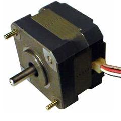
In this example we control a typical NEMA-17 stepper motor that has four wires, as shown in the image on this step. It has 200 steps per revolution, and can operate at at 60 RPM. If you don’t already have the step and speed value for your motor, find out now and you will need it for the sketch. The key to successful stepper motor control is identifying the wires – that is which one is which. You will need to determine the A+, A-, B+ and B- wires. With our example motor these are red, green, yellow and blue. Now let’s get the wiring done.